
I’m a bit of a data nerd and have been gathering metrics from my local machines for sometime now. The ability to see trends is really powerful when diagnosing problems and tuning performance.
I’m using the TIG stack – Telegraf (data collection), InfluxDB (time series database), and Grafana (visuals and alerting).
I wanted to utilize these same tools for monitoring energy usage in my house. I set out a goal to be able to see energy usage in near real time, per circuit, using mostly free software and hardware.
I ran across an excellent post on boredman’s blog that describes the hardware side of a system that very closely matches my goal. I immediately went out and acquired the pieces to play with this for myself. It wasn’t long before I had something working on my bench.
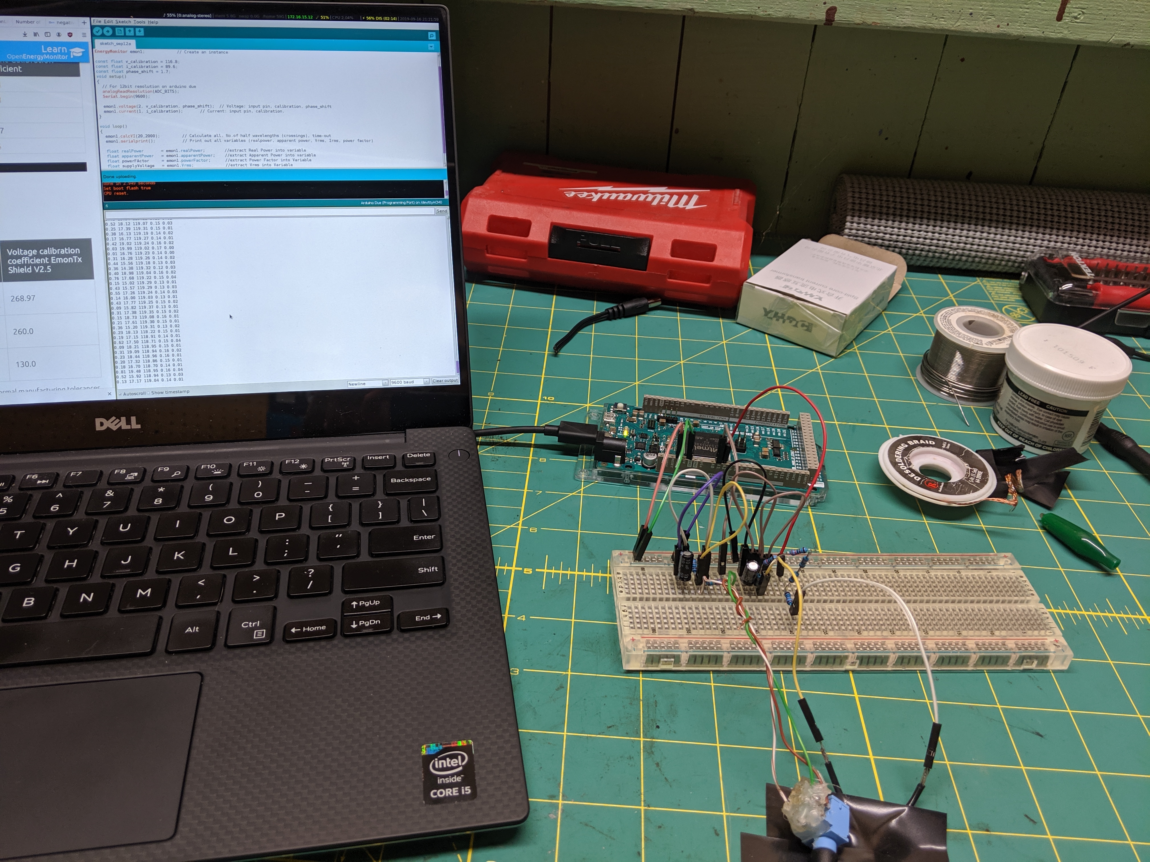
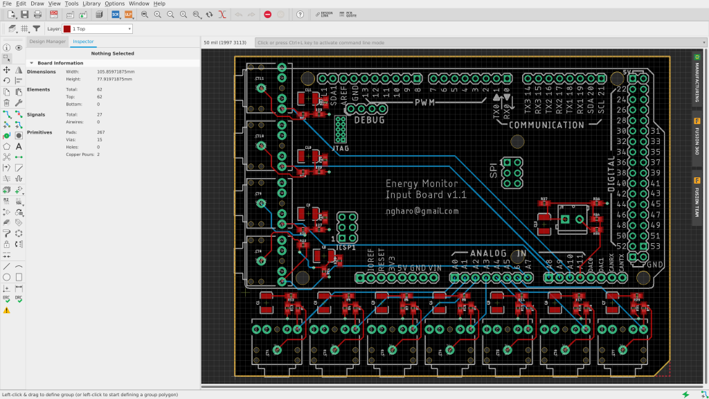
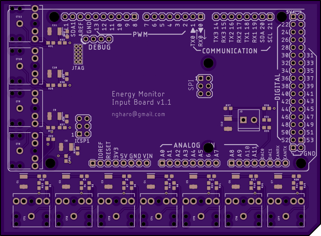
With a working proof of concept it was time to think about next steps. For me this was form factor, scaling. The Arduino Due supports 12 analog inputs. One will be consumed for Voltage measurements using an AC-AC transformer and the others will be for current measurements from current transformers on each circuit in my house. I have 22 circuits in my electrical panel — I will need two Arduinos or find better way to add analog inputs.
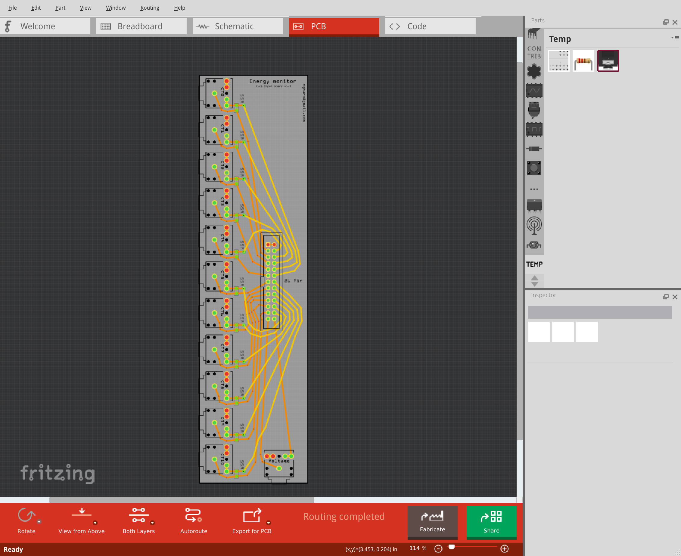
Input board 1.0
Fritzing is software for creating PCBs for newbies. Perfect. I was able to cobble together a board with CT (current transformer) and voltage inputs to a pin header thinking I could run a ribbon cable from the input board to Arduino. It wasn’t too hard to get going in Fritzing but I found it difficult to get something that looked nice and wasn’t even sure it would work. This board only has a burden resistor for each CT input.
Read more about CT burden resistors and home energy monitoring at the excellent Open Energy Monitor project
https://learn.openenergymonitor.org/
I was worried that I would be getting a lot of interference since I’m dealing with AC signals and overall felt I could do better. I iterated, this time using Eagle PCB design software. I extended to scope to capture the remaining components for each input and make it be able to plug directly into an Arduino Due.
There simple wasn’t enough room on the Arduino for 11 x 3.5mm TRS (audio jacks) inputs so I had to design the board with some margins to accommodate the inputs.
Version 1.1 was born
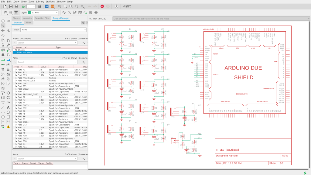
I followed this tutorial on Sparkfun for Eagle basics. You start by building your schematic in Eagle. You can pull in libraries of parts from places like Sparkfun which is really convenient. You then connect parts together using nets. Nets are like a virtual wire. Any wire/pin/whatever on Net1 will be connected.
After you’ve connected all your parts to nets, you then can switch to the PCB view. The PCB view will be a mess of parts all over but the important thing is that you can see how they’re connected by a yellow line. This is the virtual wire of the net. Organize your parts and click that ratnest button often. Don’t get too attached to one layout. I wish I had spent more time on one part of the board before moving on to duplicate my layout to the rest (ended up going back and changing all the things multiple times).
Here’s the most important thing I’ve learned when building boards: Take advantage of your copper layers!
I’m sure this is obvious to anyone but a newbie, but each layer of a PCB contains a copper plane. Most simple boards are dual layer, that means you have two planes of copper to work with. You will almost always need to connect many components to ground and power. Use one layer as a ground plane and another as power. Now components that need a ground or power connection get it almost for free, no need to route long traces!
In Eagle you choose the layer you want to work on and draw a polygon then click the ratnest button to connect components to that layer of copper. Note that for top layer components to connect to the bottom copper layer, you will need to use a via.
I submitted the board to OSH Park for fabrication and ordered all the parts off mouser. Excited to test out the board. Next post I will talk about how assembling the board using SMD components go (I have three boards on the way, bound to screw up :)). Fingers crossed.

You need a MUX (multiplexer). This one might work:
http://www.ti.com/lit/ds/symlink/mux506.pdf
Now your Arduino only needs 1 analog input (which really opens up the possibilities), and 4 or so digital outputs. You’ll need to research if this chip can handle switching AC voltages or if it’s DC-only. If it’s DC-only, you might need to pass each input through a (bridge) rectifier first.
Drop me a line if you have questions. I haven’t personally used this chip (or other MUX’es, to be honest) previously, but I understand their concept.